Wiring diagram 123SmartBMS
After the introduction of affordable LiFePO4 batteries, off-grid solutions became feasible. It is vital that such batteries are charged very carefully. In other words, they can easily be over-charged, or over-discharged. Cell-temperature and current are also very important, in order to guarantee a long life.
The 123smartbms Battery Management System (or: BMS) is primarily intended for prismatic LiFePO4-cells, but can also be adapted by the end-user for other cells like Li-Ion and LiPo, provided the cell-voltage is in the range of 2V to 5V.
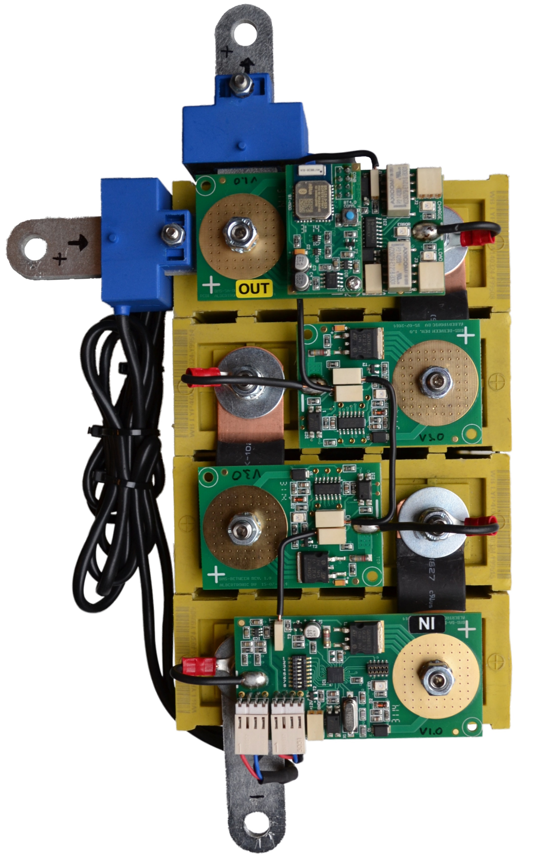
The diagram shown on the right, gives a nice overview of a wired system consisting of a single pack of batteries with BMS-boards and the current-sensors.
For a single pack of 4 batteries, the system would consist of:
1 BMS-'IN'-board
1 BMS-'OUT'-board
2 Ordinary BMS-boards
2 Current sensor
To measure current during charging and dis-charging, the current sensor should be connected in the position indicated. This is important, as this sensor is used for the so-called Coulomb-counting software, with which the BMS-controller calculates the remaining battery-capacity.
In the settings-area of the Bluetooth App, one can customise practically anything:
- Battery-capacity: 0.1 - 999 kWh.
- Cell-voltages (Vmax, Vmin, Vbypass & V-recharge)
- Cell-temperature (Tmax, Tmin in degrees Celsius)
123SmartBMS
Download the complete 123SmartBMS gen3 manual here (1.7 MB pdf file)
123SmartBMS App
Extended Module
Download the 123SmartBMS Extended Module software installer here